RC Circuits
An RC circuit is a circuit with both a resistor (R) and a capacitor (C). RC circuits are freqent element in electronic devices. They also play an important role in the transmission of electrical signals in nerve cells.
A capacitor can store energy and a resistor placed in series with it will control the rate at which it charges or discharges. This produces a characteristic time dependence that turns out to be exponential. The crucial parameter that describes the time dependence is the "time constant" R C . The far-sighted student might guess this just by observing that R C has the dimensions of time: (1 Ohm) x (1 Farad) = (1 second).
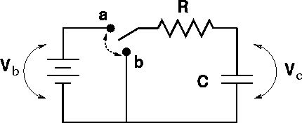
We will confine our studies to the following circuit, in which the switch can be moved between positions a and b.

Let us begin by reviewing some facts about capacitors:
When a capacitor of capacitance C is in series with a battery of voltage Vb and a resistor of resistance R, the voltage drops must be:
 ,
,
which is a statement that the voltage gained going across the battery must equal the voltage drop across the capacitor plus the voltage drop across the resistor. An equation where the rate of change of a quantitity (DQ/Dt) is proportional to the quantity (DQ) will always have an exponential solution. We consider two instances:
Discharging the capacitor: The capacitor initially is connected (switch in position a) for a long time, and is then disconnected by moving the switch to b at time t = 0. The capacitor then discharges, leaving the capacitor without charge or voltage after a long time.
Charging the capacitor: The switch is in position b for a long time, allowing the capacitor to have no charge. At time t = 0, the switch is changed to a and the capacitor charges.
| Discharging | Charging | |
| Charge | ||
| Current | ||
| Voltage |
Here, Q0, V0 and I0 refer to the charge, voltage and current of the capacitor in the instant after the switch is thrown. The time t is the characteristic time of the decay, t = RC. When confronted with an RC problem, the best strategy is the following:
Decide what the charge across the capacitor was just before the switch was thrown. Since the charge can not change instantly, this is the charge just after the switch is thrown.
Decide what the charge is long after the switch is thrown.
Pick the exponential form for the charge Q(t) to satisfy the correct initial and final charges.
The voltage across the capacitor can be found through, V = Q/C. The voltages across the other elements can be found with the help of Kirchhoff's first law.
The current through a capacitor must always decay and end up at zero. The initial current can usually be ascertained with the help of Ohm's law, V=RI.
The characteristic time t = RC tells you that the charging/discharging is slower with a larger resistor or capacitor. This makes sense, because a larger resistor impedes the flow of current; thus slowing the charging/discharging, and a larger capacitor holds more charge; thus requiring more time to charge.
Every educated person should have a good feeling for exponential functions. (Sketches of the charge Q(t) for charging and discharging capacitors could be shown here.)