Main Design Project
Introduction
|
|

In order to gain some experience with using macros we will exploit some of the features of our boards to construct a counter that will count from 0 to 9 with the counts displayed in one of our four 7-segment displays. Which of the displays is used will be selected by our sliding switches. In addition we will instrument one of the push buttons to reset the counters momentarily to all zero’s. The DI01 board is constructed in such a fashion that individual segments of the four displays are connected in parallel and are turned on when the particular connection is grounded. The choice of which of the four displays to activate is made by bringing the chosen display’s anode to a positive logic value. Read over the description of the DI01 module, in particular the description of the seven segment displays and how the individual segments combine to form numbers.
Macros
In your design you will need to use several macros one of which is the decimal counter you constructed during last weeks lab and another is a routine to translate the four bit output from the decimal counter into the pattern of 0’s and 1’s corresponding to the activated segments on a 7 segment display. This will be the file hex2led.vhd. A third macro will divide the 50 MHz clock down to something that we can easily display and verify.
Procedure
|
Figure 2: Schematic of divide by 2^24 circuit. |

Open Project Navigator and start a new project choosing “schematic” as the highest level module. Verify that the Device Family is “Spartan2”, the Device “xc2s30” and the Package “tq144”. Find and add source files for the counter you made in last weeks lab. Create a schematic symbol for your counter and verify that it is available as a symbol on the schematic entry page. Next find the file “hex2led.vhd” and add it as a source to your project. If you cannot locate it, ask your instructor. Make a symbol out of it and verify that it too is available as a symbol on the schematic entry page. Take some time to read the VHDL code in “hex2led.vhd” and note the advantages of this method of specifying the circuit. A few lines take the place of a large number of logic gates. Your “Navigator” page should look something like Figure 1, where “Maine” is the name of the schematic file where the design will take place.
We need to make one more macro: something that will take the 50 MHz clock as input and will divide it down to a viewable rate, say ~3 Hz. We need a device that will divide our clock by ~16 x 106 or 224. This is easily done by cascading two counters, one with16 bits, the other with 8 and counting the highest order bit. Create a new schematic “source” for the project that should look like the schematic in Figure 2. The counters in the schematic are chosen from the “Counters” in the “Symbols” menu. After verifying that the design has no errors, create a schematic symbol to represent this circuit.
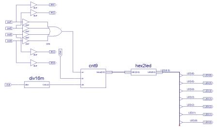
Next return to the main schematic page and assemble your macros and all the necessary logic circuitry for your project. You will need the macro for the decimal counter, the macro for the “divide by 2^24” and the macro for the “hex-to-led”. Your assembled circuit should look something like the schematic in Figure 3 . Next, consult the DI01 Manual and the Di01/D2XL pin correspondence chart and determine the pin numbers for the clock, the seven segment counter, the four anodes, the buttons and the switches. Go to “Assign Package Pins” and make the appropriate assignments. We will not try to simulate this design but, proceed directly to “Configure Device”. If there are no errors in any of the intermediate steps your design should download successfully and work as designed.
You should observe a counting rate of ~2 Hz on all seven segment counters chosen by a corresponding switch. In addition, while the counters are counting, they can be reset to 0 by holding down push-button switch number 1.
Supplementary Exercises
LED Switch
Go back to your main schematic and change the design so that the LED opposite a switch lights up when the switch is closed. You will need to make some additions to the logic of the design as well as adding some pin assignments.
|
Figure 3: Full Design Schematic. |
Divide by 2^N
|
Figure 4: Navigator pages with "div23" vhdl code shown. |

Our Macro to divide down the 50MHz clock is somewhat inelegant. To get some practice with VHDL add a new source file to the project, say “div23” of type VHDL. This should produce a template which you can modify to perform your desired function. An example of such a code is shown in Figure 4. Copy the code into your design and create another symbol. Verify that this symbol is available to the design and then modify your design to use this new “divider” macro. Note that this one is designed to divide the rate by 2^23. You will need to change your pin assignments if you use different symbols for the input. After you have checked that your design has no errors, load it into your FPGA and verify its proper operation. If it works satisfactorily, modify the “div23” file to divide by a different number, say 2^24, and verify that the counting rate changes in the expected way.