|
|
|
Development and Assessment of Bleed Boundary Conditions in Supersonic Boundary Layer Flows |
|
Background Bleed Boundary Condition Papers References |
|
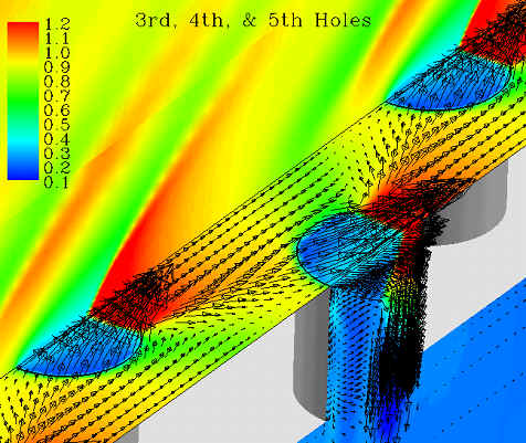
For many aerodynamic devices that operate in the supersonic regime, boundary-layer distortion due to surface curvature and incident shock waves are controlled by bleeding away the low-momentum air next to the wall into a plenum through discrete holes. Within the field of Computational Fluid Dynamics (CFD), two approaches are possible for analyzing bleed systems. The first approach is to simulate the flow in the entire bleed system, including the flow through each bleed hole and the plenum (similar to the plot shown above). The advantage of this approach is that the physics of the bleed process is simulated using first principles. However, in order to accurately simulate the complex flow through the holes and in the plenum, a very large number of grid points or cells are needed. An alternate approach is to model, instead of simulate, the flow through the bleed holes and the plenum. In this approach, the bleed holes and plenum are removed from the simulation and a model for the flow through the holes is applied at the surface where bleed is desired. The model chosen to represent the flow through the hole is a boundary condition that is applied in place of the wall boundary condition. The complexity of the model is one of the issues studied and it can vary greatly with the goal being to accurately capture the physics of the flow above the plate with the simplest model and the fewest number of grid points. Using bleed boundary conditions to model the bleed process results in a significant savings in terms of the number of grid points needed to model a flow with bleed. For example, in one of the simulations studied the flow through four (half) holes on a flat plate in the presence of an incident shock was originally accomplished with approximately 2 million grid points. The first application of the bleed boundary conditions maintained the same essential grid structure as the full simulations, but the grids used for the holes and the plenum were not needed. At the hole locations, simple bleed boundary condition were applied to model the flow through the hole. The simulation for this 1 million grid points. Later, the bleed boundary conditions were applied to the coarsest case possible: each bleed hole was modeled using only one grid cell. In this coarse grid case, only about 5,500 grid points were needed to model the flow (a significant reduction). From the CFD perspective, if the flow can be accurately modeled using few grid points it is preferred. It results in a savings in terms of memory (not as much of an issue these days) and in time (money). Additionally, using bleed boundary conditions allows the user to study different patterns, spacing and location of bleed holes with only a slight modificatiions needed to the grid. The objective of this research was to develop, implement a set of bleed boundary conditions to replace the need for modeling the flow through the holes and plenum. With these bleed boundary conditions in place and using a simple discharge coefficient to control the bleed rate (known from the detailed simulations), it was shown that the main features of the flow, mainly the downstream boundary layer profiles, could be adequately modelled with a minimum of grid points. The next step in this research is to develop a general model for determining the discharge coefficient so that this approach can be applied to a variety of flow configurations.
|