


Next: About this document ...
PHY294H - Lecture 34
In a series LRC combination with applied
AC voltage,
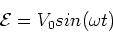 |
(1) |
The current in the circuit is given by,
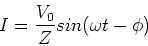 |
(2) |
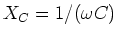
The phase,  is given by,
![\begin{displaymath}\phi = tan^{-1}[{X_L -X_c\over R}]
\end{displaymath}](img4.gif) |
(3) |
and the impedance, Z, is given by,
|
Z = [(XL-XC)2 + R2]1/2
|
(4) |
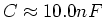
where
 and
and
 .
.
LRC circuit demo
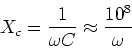
We have an LRC box, with L fixed at L=1Hand R, C, and  variable. We
set
variable. We
set
 and
and
 .
We then have,
.
We then have,
 |
(5) |
 |
(6) |
We then expect that resonance will occur
at
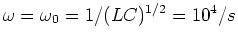 .
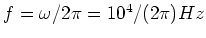
The frequency in Hertz is
.
The frequency in Hertz is
 For
For
 ,
the capacitor has higher
impedance than the inductor. The current in the
circuit should be ahead of the voltage. This means that the
phase should be negative as it is. For
,
the capacitor has higher
impedance than the inductor. The current in the
circuit should be ahead of the voltage. This means that the
phase should be negative as it is. For
 ,
the inductive reactance is higher than the capacitive
reactance, so the applied voltage leads the
current in the circuit. In this case, the phase
is positive. The voltage across the resistor
is in phase with the current across the resistor,
so we use the voltage across the resistor
to illustrate the phase of the current as a function of
frequency. At all frequencies, the voltage
across the capacitor should lag the current
by
,
the inductive reactance is higher than the capacitive
reactance, so the applied voltage leads the
current in the circuit. In this case, the phase
is positive. The voltage across the resistor
is in phase with the current across the resistor,
so we use the voltage across the resistor
to illustrate the phase of the current as a function of
frequency. At all frequencies, the voltage
across the capacitor should lag the current
by  ,
while the voltage across the inductor
leads the current by .
,
while the voltage across the inductor
leads the current by .
Power dissipated in an LRC circuit
As we noted before ideal inductors and capacitors
only store and release energy, they do not
dissipate energy. The energy is only dissipated
in the resistor. The power dissipated is then,
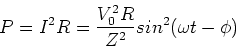 |
(7) |
if we average the sine function over a period,
we get the average power (also called the rms power),
 |
(8) |
The power dissipation is maximum at resonance, where
Pav = V02/(2R). A plot of the power as
function of frequency shows a resonant peak,
as expected. This peak is higher for smaller
resistance. Two measures of the width
of the resonant peak are: The half width,
which is the frequency width at which the
resonant peak reduces to half of its
peak value,
 .
It is
easy to show that,
.
It is
easy to show that,
 |
(9) |
The second measure is the quality factor, Q,
which is defined by,
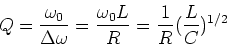 |
(10) |
Power factor
Often the power dissipated in an LRC circuit is
given as,
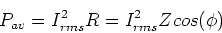 |
(11) |
This is true as we proved last lecture that
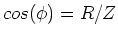 .
The term
.
The term  is
called the power factor as it gives
the reduction in power as compared to
one in which the entire impedance Zcontributes to the dissipation. The
power factor tells us
what fraction of the load is resistive.
is
called the power factor as it gives
the reduction in power as compared to
one in which the entire impedance Zcontributes to the dissipation. The
power factor tells us
what fraction of the load is resistive.
Rectifiers and filters
Half-wave and full-wave rectifiers.
AC and DC filters using capacitors and
inductors.
Impedance matching
If we want to deliver
maximum power from a
source circuit with impedance Z1
to a load circuit with impedance Z2,
it is best to use,
 |
(12) |
Next: About this document ...
Phil Duxbury
2002-11-02