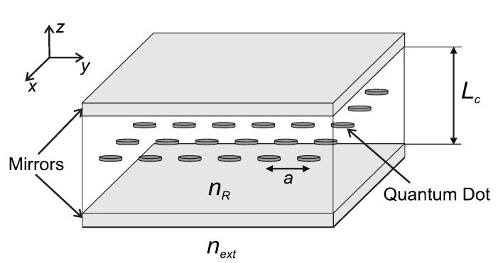
Fig. 1 Scheme of our system: An ideal quantum dot lattice is embedded in a planar microcavity of length Lc and refractive index nR.
Bragg polariton and quantum
computation in an array of quantum dots in a cavity
From
nontrivial quasi-particles towards scalable quantum computer
Fig.
1 Scheme of our system: An ideal quantum dot lattice is embedded
in a planar microcavity of length Lc and refractive index
nR.
Bragg polariton:
|
There is a long standing interest in designing novel nanostructures which would allow to tailor quasi-pariclte properties, especially its mass. Recently we have shown that in a two-dimensional array of quantum dots embedded in a planar cavity the Bragg polariton forms. Its mass is very light (up to 10-8 m0, m0 being the bare electron mass) [1] and it is quite robust against disorder [2], especially the oscillator strength one (describing on-site light-matter coupling). |
|
|||
|
|
|
|||
|---|---|---|---|---|
|
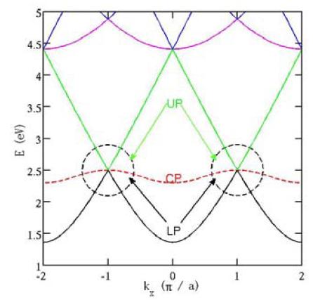
Fig. 2 Left: Scheme of photonic branches (solid lines) in a repeated zone scheme. The red dashed line indicates the exciton energy band. Bragg polaritons are obtained by tuning the exciton energy at the zone boundary where photonic branches cross. Upper, Lower, and Central Polariton modes (indicated by UP, LP, and CP) appear due to the light-matter coupling. |
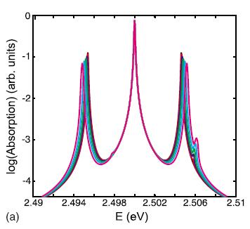
Fig. 2 Right: Polariton absorption spectrum in a logarithmic scale for oscillator strength disorder with variance from 0% (black, no side peaks) to 50% (magenta, strongest side peaks) increasing by steps of 10%. Exciton energy is in resonance with photon energy at M-point of the first Brillouin zone. |
|||
|
|
||||
|
|
||||
|
Scalable quantum computer: Quantum computing has become a very active research field recently since it aims towards the exploitation of nontrivial properties of quantum physics for a computational speedup, e.g. search algorithms. The spin of a charge particle is widely accepted as very good qubit (quantum bit) in the solid state. We have proposed a scalable computer which consits of an array of such qubits (charges in quantum dots) and which enables computation (gate operations) with high fidelity [3]. |
|
|||
|
|
|
|||
|
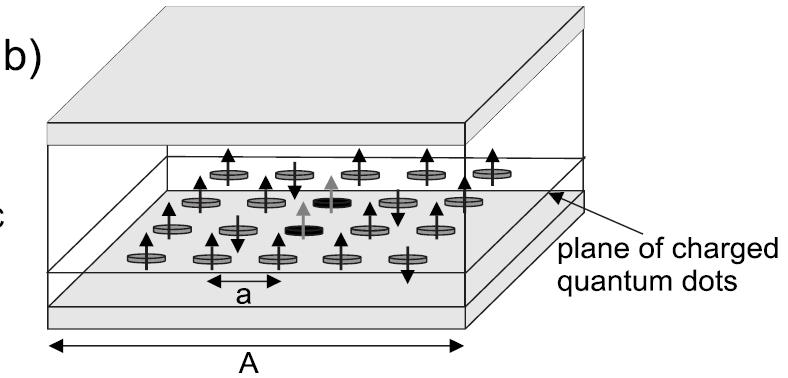
Fig. 3 Left: Scheme of the spin lattice composed of charged quantum dots in a planar cavity. Two dots, whose is in resonance with the cavity mode, are highlighted. |
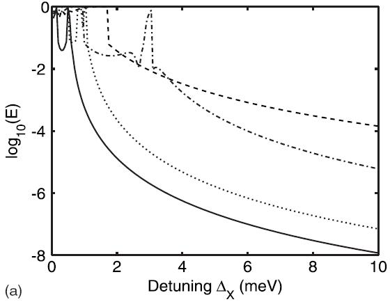
Fig. 3 Right: Logarithmic plot of the computation error E as a function of the detuning DX between the two dots resonant with the cavity and the others.
|
|||
|
|
||||
|
Literature |
||||
[1] E. M. Kessler, M. Grochol, and C.Piermarocchi, Phys. Rev. B 77, 085306 (2008).
[2]
M. Grochol and C. Piermarocchi, Phys. Rev. B 78, 035323
(2008).
[3] M. Grochol and C. Piermarocchi,
Phys. Rev. B 78, 165324 (2008).