Phase problem II: Centrosymmetric vs. Acentric
Phase problem
Shift in real space
Centrosymmetric vs. Acentric
Interactive examples
Single atom
Pair of atoms
One atom in unit cell
Two atoms in unit cell
Goto
Contents
The centrosymmetric structure (left) has two atoms, with the silicon at a special position. The acentric structure (right) is distinguished only by a slight shift of the silicon away from the center of symmetry.
Sample structure in R-3 R-3 5.00 5.00 5.00 80.0 80.0 80.0 SI 0.50 0.50 0.50 O 0.10 0.05 0.30 |
Sample structure in R3 R3 5.00 5.00 5.00 80.0 80.0 80.0 SI 0.49 0.49 0.49 O 0.10 0.05 0.30 O 0.90 0.95 0.70 |
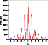
The Fourier transforms were calculated for one unit cell along a line through reciprocal space parallel [111]. The left image below shows the intensities of the two structures superimposed. Hardly any difference is visible, just a few tiny blue spots show at the outer part of the Fourier transform. The complex structure factors for both structures are shown in the middle and right picture, respectively. To get a full screen version, click on the corresponding image.
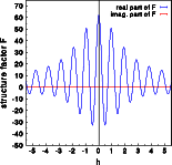
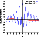
The real parts (blue) are practically identical, the imaginary part (red) of the centrosymmetric structure (middle image) is zero while the corresponding imaginary part of the acentric structure is non-negative. Notice that the imaginary part does not reflect the oscillations visible for the real part. These oscillations are caused by the interference of the six oxygen atoms in the unit cell. The oxygen does not contribute to the imaginary part, this is only due to the silicon atom moved by -0.01,-0.01,-0.01 ! Accordingly the imaginary part oscillated slowly with a period of ten reciprocal lattice constants along [111].
Last, lets have a detailed look again at the phase of the scattered wave in both situations.
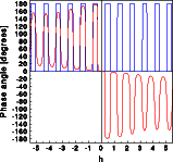
The phase of the wave scattered by the centrosymmetric structure is zero or 180 degrees (blue curve). The absolute value of the phase scattered by the acentric cell (red ) is similar, especially in the center of reciprocal space. It can, however, assume any numerical value between -180 and + 180 degrees. Furthermore the phase of hkl and -h-k-l has the opposite sign. Unfortunately Friedel's law has this difference disappear, which makes crystallography both difficult and exciting.
The students will learn from this exercise:
- Slight deviation from centrosymmetry causes only minute changes of the real part of the scattered wave, while the imaginary part, and thus the phase, may vary considerably.
- The intensity will change only very little, which makes it difficult to distinguish between a centrosymmetric and an almost centrosymmetric structure.
Possible extensions of this exercise:
- Have the students shift the silicon by +0.01,+0.01,+0.01 and ask them to explain the differences that follow. A discussion on absolute configurations may follow.