LRC
circuits
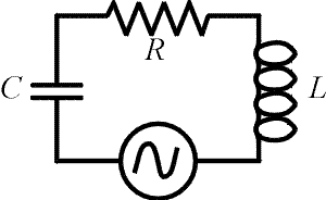
 Here we
consider circuits with an AC power supply and all three
fundamental elements, a resistor, an inductor and a
capacitor. The same current flows through each element at
every instant in time. The voltages across the four
elements must sum to zero when travelling around the loop
at any instant as well. Although the voltages across all
the elements rise and fall with the same frequency, they
do not all have the same phase. When two
signals have the same frequencies but different phases,
the sine waves representing the signals begin
oscillations at different times. There is an offset of
the patterns. For instance if we say one signal is 90
degrees behind another, that would mean that the sine
wave would be displaced by one fourth of a period. Here we
consider circuits with an AC power supply and all three
fundamental elements, a resistor, an inductor and a
capacitor. The same current flows through each element at
every instant in time. The voltages across the four
elements must sum to zero when travelling around the loop
at any instant as well. Although the voltages across all
the elements rise and fall with the same frequency, they
do not all have the same phase. When two
signals have the same frequencies but different phases,
the sine waves representing the signals begin
oscillations at different times. There is an offset of
the patterns. For instance if we say one signal is 90
degrees behind another, that would mean that the sine
wave would be displaced by one fourth of a period.
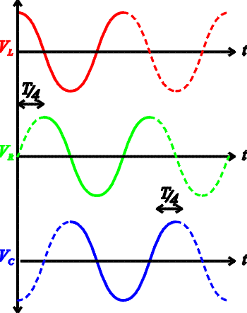
 In the figure on the right, the voltage drop
across each element is shown as a function of time. The
green line, which is the voltage drop across the
resistor, also demonstrates the phase of the current. One
can see that VL
preceeds the current by one fourth of a period. This is
because the inductors voltage drop is largest as the
current is rising since it is proportional to DI/Dt.
The opposite is true of the voltage across the capacitor Vc
as it keeps rising until the current is no
longer forward. This is because it is proportional to the
charge which grows as long as the current is positive.
Thus VL and
Vc are 180
degrees out of phase, which means they simply have
opposite signs. In the figure on the right, the voltage drop
across each element is shown as a function of time. The
green line, which is the voltage drop across the
resistor, also demonstrates the phase of the current. One
can see that VL
preceeds the current by one fourth of a period. This is
because the inductors voltage drop is largest as the
current is rising since it is proportional to DI/Dt.
The opposite is true of the voltage across the capacitor Vc
as it keeps rising until the current is no
longer forward. This is because it is proportional to the
charge which grows as long as the current is positive.
Thus VL and
Vc are 180
degrees out of phase, which means they simply have
opposite signs.
The impedance
is the ratio of the peak voltage of the source to the
peak current. This impedance depends on the frequency of
the source as well as the values of L,
C and R.
The impedance Z (derivation
in next page) can
be thought of as the AC analog to resistance.

The impedance is at a
minimum when the reactance of
the inductor, XL
= 2pfL,is
canceled by the reactance of the capacitor, XC
= 1/(2pfC). This
is the same resonant condition as discussed for LC
circuits previously.
Examples AC
circuits's index
|


 Here we
consider circuits with an AC power supply and all three
fundamental elements, a resistor, an inductor and a
capacitor. The same current flows through each element at
every instant in time. The voltages across the four
elements must sum to zero when travelling around the loop
at any instant as well. Although the voltages across all
the elements rise and fall with the same frequency, they
do not all have the same phase. When two
signals have the same frequencies but different phases,
the sine waves representing the signals begin
oscillations at different times. There is an offset of
the patterns. For instance if we say one signal is 90
degrees behind another, that would mean that the sine
wave would be displaced by one fourth of a period.
 In the figure on the right, the voltage drop
across each element is shown as a function of time. The
green line, which is the voltage drop across the
resistor, also demonstrates the phase of the current. One
can see that VL
preceeds the current by one fourth of a period. This is
because the inductors voltage drop is largest as the
current is rising since it is proportional to DI/Dt.
The opposite is true of the voltage across the capacitor Vc
as it keeps rising until the current is no
longer forward. This is because it is proportional to the
charge which grows as long as the current is positive.
Thus VL and
Vc are 180
degrees out of phase, which means they simply have
opposite signs.