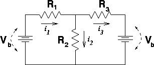
When to use Kirchoff's laws Although Kirchoff's laws were used to derive the simple relations for adding resistors in series and parallel, not all problems can be broken down into such simple pieces. Below are three diagrams which may need to be solved (e.g. given the resistances and voltages of the batteries, find all the currents).
The left-side figure can be treated by breaking up the circuit into pieces and applying the rules for adding resistances in parallel and series. The resistors R3, R4 and R5 can be treated as a single resistor with resistance R345, which can then be added in parallel with R2, to give an effective resistance R2345. The battery sees a net resistance R = R1 + R2345. The middle and right-side figures can not be solved by such a strategy. Instead, one must write down Kirchoff's laws then solve the equations.
Remember that one gains the voltage of the battery when travelling from the small hashes and leaving from the large hashes in the battery. One could also imagine writing equations for a third loop, that travels all the way around the circuit, through both batteries. However, such an equation is merely a linear combination of Eq. 2 and Eq. 3 above. |


 For instance consider the
right-side figure. The 3 currents through the 3
resistors i1,
i2
and i3
are unknown. The three unknowns can be found by
solving 3 equations: